ID meets OD
The receiving section’s inside diameter must be considered against the next section’s outside diameter, including tolerances and any wear guides.
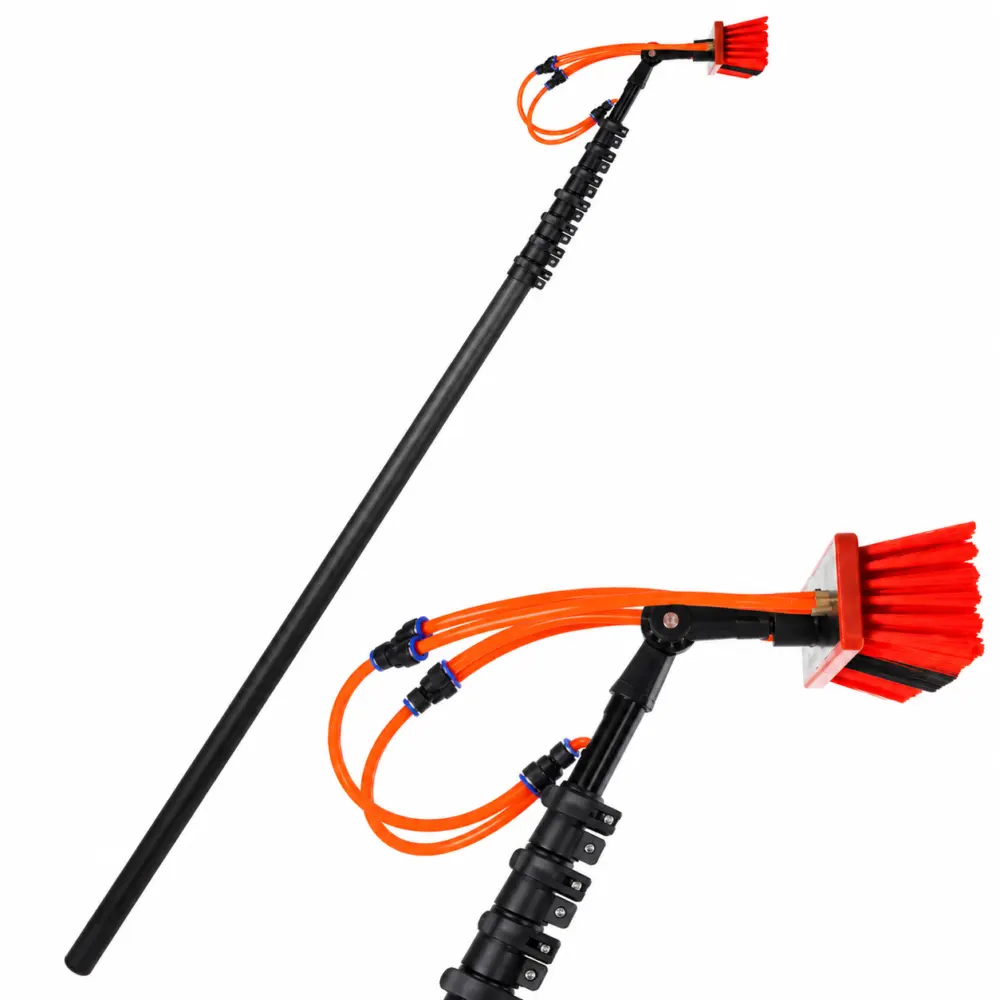
Images show configuration references. Final appearance is agreed with your sample.
FACTORY DIRECT / MADE TO YOUR SPECIFICATION
Any custom extended length from 6 to 20 metres. Configure the tubes, clamps and brush connection around your equipment.
Price is based on dimensions, material, quantity and accessories. Share the specification below to start a technical enquiry.
BUILD YOUR ENQUIRY
Choose any length between 6 and 20 m, including intermediate lengths such as 9.5 m. The feet value updates automatically.
This prepares your enquiry details. It does not place an order or send a message.
WATER-FED POLES / SPECIFICATIONS
| Parameter | Custom specification |
|---|---|
| Extended pole length | Any custom length from 6–20 m / approx. 19.7–65.6 ft |
| Construction | Nested carbon fibre round tubes with matched sliding fits |
| Section count & closed length | Configured for the requested extended length, transport length and overlap |
| Tube OD, ID & wall | Custom dimensions; final tube schedule agreed before production |
| Clamps | Lever-clamp layout and colour to be agreed with the selected design |
| Brush connection | Connection dimensions and brush or angle-adaptor requirements to drawing or sample |
| Water hose | Internal or external route to be specified; hose bore and fittings agreed for the system |
| Finish | Gloss or matt finish; appearance sample to be approved |
| Weight & stiffness | Dependent on length, tube layup and accessories; confirmed for the selected build |
| Supply scope | Bare tube sections, machined components or an assembly with agreed accessories |
| Machining | Cutting, drilling and connector preparation to approved drawings |
Brushes, hoses, clamps and adaptors are included only when listed in the quotation. Images illustrate configurations; they do not establish a tested load or compatibility rating.
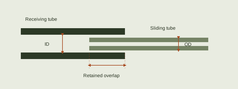
The receiving section’s inside diameter must be considered against the next section’s outside diameter, including tolerances and any wear guides.
The joint must retain its designed overlap when extended. Mark the agreed extension limit; do not recover extra reach by reducing overlap without a design review.
Specify the clamp contact zone, required holding behaviour and permitted local compression. Tightening a clamp harder is not a substitute for a suitable fit.
Use the receiving tube’s inside diameter and the sliding tube’s outside diameter. The example values are for explanation, not a recommended fit.
Minimum clearance uses the smallest receiving ID and largest sliding OD. Maximum clearance does the reverse.
This calculation does not approve an assembly. Ovality, straightness, surface finish, wear, temperature, overlap and the clamp design also affect fit and service performance.
Dimensions in millimetres unless shown otherwise. Scroll sideways on a small screen.
| Item | Confirm for your enquiry |
|---|---|
| Length | Required actual extended length and transport / closed length |
| Sections | Count, individual lengths, diameters, wall and retained overlap |
| End tool | Brush and neck mass, attachment geometry and operating orientation |
| Water route | Hose routing, fittings and required spare hose when extended |
| Finish & wear | External finish, sliding surfaces, guides, stops and clamp zones |
| Acceptance | Sample fit, joint security and agreed deflection / durability tests |
MORE APPLICATIONS / SAME MANUFACTURING KNOW-HOW
FROM REQUIREMENT TO PRODUCTION
Confirm dimensions, intended use, mating interfaces, quantity and which accessories are included.
Agree sample requirements and acceptance checks for fit, finish, dimensions and the relevant assembly behaviour.
Review tooling or sample costs, production price, lead time, packing and delivery terms before placing an order.
You don’t need a complete specification to start a conversation. Tell us the application and what you know so far.
sales@fibreparts.com ↗