Bending and image movement
Length alone does not describe camera stability. Tube stiffness, joint clearance, mounting offset and operating angle all affect image movement. Define the acceptable movement for your inspection task.
FIBRE PARTS / APPLICATION-LED MANUFACTURING
Custom telescopic pole assemblies for roof inspections, elevated imaging and equipment integration. Start with the camera, the mounting interface and the required reach.
Made to an agreed specification. Quoted by dimensions, quantity and supply scope.
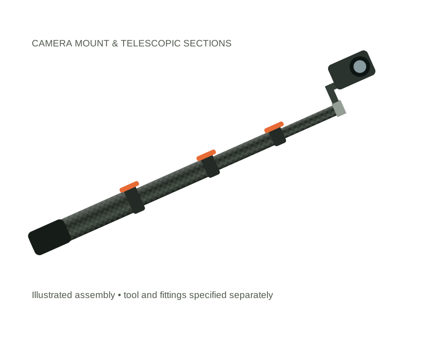
6 m (19.7 ft) and 10 m (32.8 ft) are useful reference lengths for an initial enquiry. They are starting points for a custom design, not stocked models or an approved payload rating. Tell us if you need a different length.
| Parameter | Specification to discuss |
|---|---|
| Extended length | Reference requests: 6 m / 19.7 ft and 10 m / 32.8 ft. Final configuration reviewed against camera mass and use. |
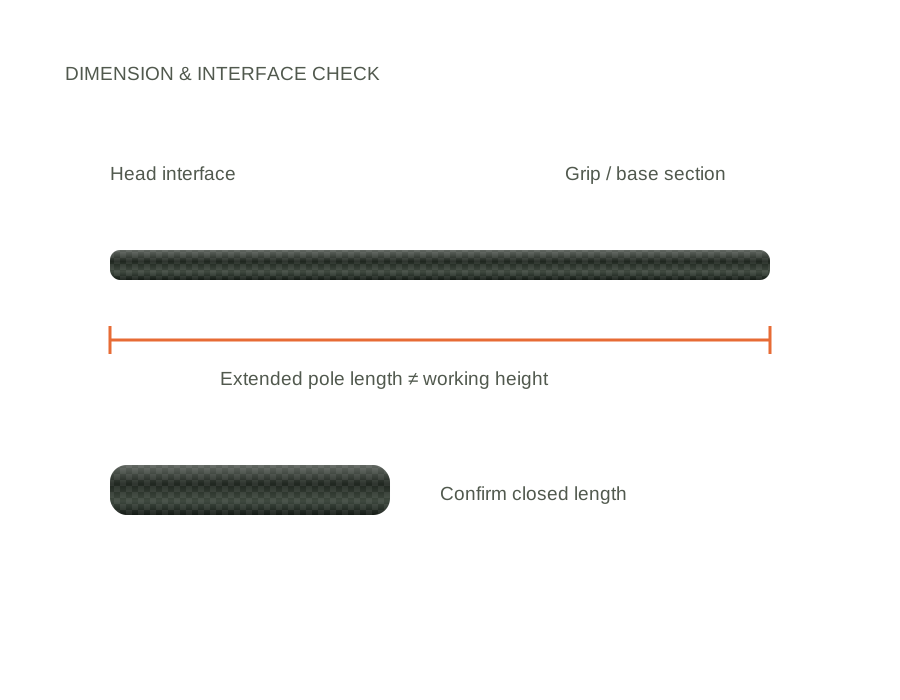
| Closed length & section count | State the transport-length limit in mm. Section count and retained overlap are then agreed. |
| Head interface | A 1/4-inch photographic thread is one option to discuss. Confirm thread pitch, engagement, mounting face and the complete camera adapter drawing. |
| Tube dimensions | OD, ID, taper, wall thickness and joint clearances defined for the assembly; no one tube size fits every length. |
| Camera and mount mass | Provide the combined mass and centre-of-gravity offset. Permitted payload requires evaluation at the intended extension and angle. |
| Cables & finish | Internal or external routing to be reviewed. Matt or gloss surface; grip, clamps and base cap listed in the supply scope. |
| Supply scope | Pole and agreed fittings only unless the quotation specifically includes other equipment. Camera, monitor and pan/tilt unit are not included by default. |
Length alone does not describe camera stability. Tube stiffness, joint clearance, mounting offset and operating angle all affect image movement. Define the acceptable movement for your inspection task.
The camera must remain aimed as sections are extended and locked. Agree anti-rotation needs, clamp zones and repeatable locking checks; a clamp should not need excessive force to hold a section.
Allow for connectors, cable slack and the full retraction path. Check snag points and access to the camera mount. Internal routing must not compromise joint engagement.
Do not assume a matching nominal thread guarantees fit. Confirm pitch, insertion depth and mounting contact area. Discuss bonded or mechanically retained inserts rather than an unsupported thread in a thin tube wall.
No camera or electronic system is included unless explicitly listed in the agreed quotation. We focus on the pole structure and its interfaces.
A generic payload would be misleading. Send the camera mass, mount offset, operating angle and required extension so that a sample and acceptance checks can be agreed.
No. The stated dimension is the extended pole itself. Working height depends on the operator, angle, mounting arrangement and safe access conditions.
Send dimensions, quantities, mating-part details and delivery country. State whether you need bare tubes, fitted sections or an assembled pole.
Confirm material, finish, interfaces and acceptance checks. Evaluate the actual assembly before approving the production specification.
Separate tube or assembly costs, bought-in accessories, tooling, samples, packing and shipping. Lead time is confirmed against the final build.
SEND THE INTERFACES, NOT JUST THE LENGTH
Mark the dimensions that affect fit. Include tool or mating-part details, the required quantity and any acceptance checks. Attach your drawing when sending the enquiry email.
Carbon fibre is electrically conductive. These products are not offered as electrically insulated equipment. Keep away from overhead power lines and follow the operating requirements for the complete assembly.
YOUR BUILD / YOUR REQUIREMENTS
Enter the dimensions you know. If an interface still needs review, say so in the notes. We will confirm the specification before production.
This adds details to the email enquiry below. It does not place an order or send a message.
EXPLORE OTHER POLE APPLICATIONS
You don’t need a complete specification to start a conversation. Tell us the application and what you know so far.
sales@fibreparts.com ↗