Match the mating surfaces
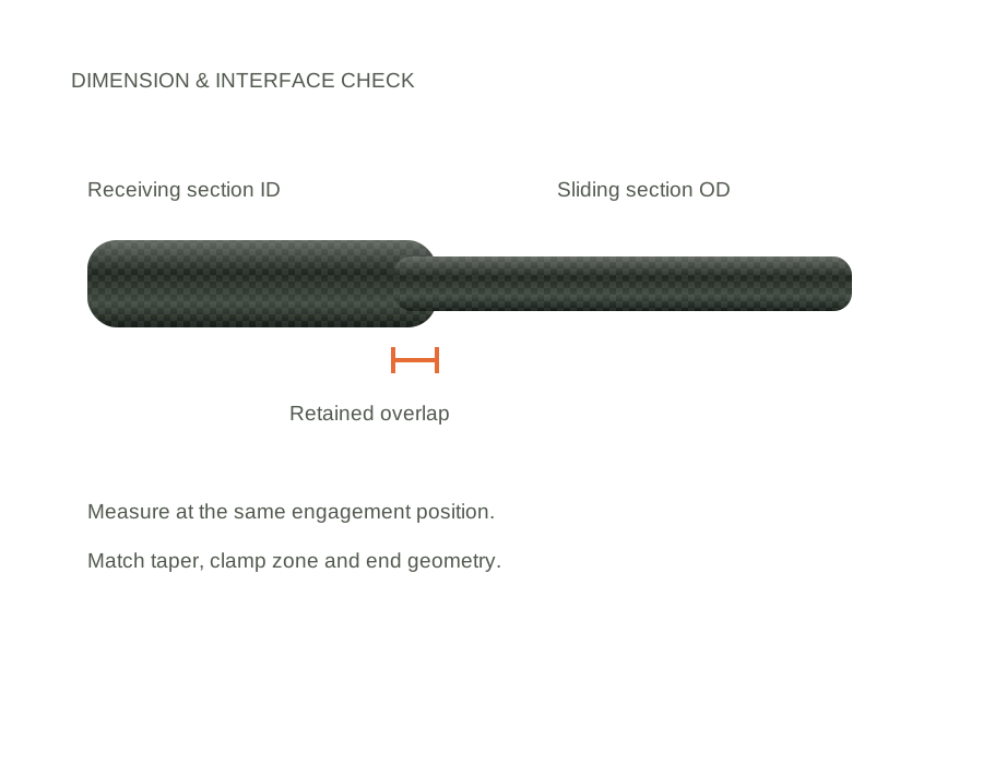
A sliding section and a receiving section form a pair. Compare the inside diameter of one with the outside diameter of the other at the same joint position; account for taper and finish thickness.
FIBRE PARTS / APPLICATION-LED MANUFACTURING
Replacement tube sections and modular extensions made around your drawing or sample. Match the joint, the clamp zone and the full assembly—not just the outside diameter.
Made to an agreed specification. Quoted by dimensions, quantity and supply scope.
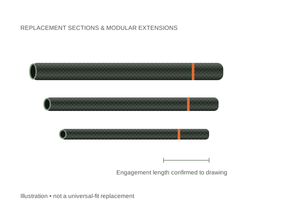
A replacement restores an existing assembly. An extension changes its overall geometry and loading. Tell us which you need so that the right dimensions and checks are included.
| Parameter | Specification to discuss |
|---|---|
| Section length | Specify in mm. 1,000 / 1,200 / 1,500 mm are enquiry examples, not a stock-size list or compatibility guarantee. |
| OD and ID | Measure at the entry, clamp area and specified engagement positions. Include the measurement positions on the drawing. |
| Vacuum section formats | 44 mm and 50 mm are useful system-diameter references for gutter-vacuum enquiries. Confirm actual tube OD, bore, cuff and seal fit before manufacture. |
| Wall / taper | Provide wall thickness and taper at defined stations. Appearance and a single diameter measurement are not sufficient to match an existing section. |
| Retained overlap | State required engagement in mm, stop position and any maximum-extension marking. Do not calculate usable extension from total tube length alone. |
| Clamp and end features | Specify clamp type, fixing holes, reinforced zones, end rings, insertion stops and base cap requirements. |
| Finish and supply | Matt or gloss; bare tube, machined tube or section with agreed fittings. Accessories and fit verification are quoted explicitly. |
A sliding section and a receiving section form a pair. Compare the inside diameter of one with the outside diameter of the other at the same joint position; account for taper and finish thickness.
A clamp creates local compression. Layup, wall thickness and reinforcement near the clamp must be considered alongside the main tube stiffness. More clamp force does not correct an unsuitable fit.
Adding a section increases lever length and changes balance and bending. Confirm which base section receives it, the combined extension and the intended tool load before approving the sample.
For suction sections, check the bore, seal and internal step at the joint. A joint that fits mechanically can still leak or obstruct debris. Discuss an assembly fit and leakage check.
Compatibility must be checked against a drawing or sample. We do not claim universal fit or affiliation with other pole brands.
An undamaged mating section and a dimensioned drawing are more useful for defining the original fit. Clearly identify wear, cracks and distortion so these are not copied into the new specification.
Its total length is not its usable addition. Subtract the retained overlap and account for the specific joint arrangement; confirm the result on the assembly drawing.
Send dimensions, quantities, mating-part details and delivery country. State whether you need bare tubes, fitted sections or an assembled pole.
Confirm material, finish, interfaces and acceptance checks. Evaluate the actual assembly before approving the production specification.
Separate tube or assembly costs, bought-in accessories, tooling, samples, packing and shipping. Lead time is confirmed against the final build.
SEND THE INTERFACES, NOT JUST THE LENGTH
Mark the dimensions that affect fit. Include tool or mating-part details, the required quantity and any acceptance checks. Attach your drawing when sending the enquiry email.
Carbon fibre is electrically conductive. These products are not offered as electrically insulated equipment. Keep away from overhead power lines and follow the operating requirements for the complete assembly.
YOUR BUILD / YOUR REQUIREMENTS
Enter the dimensions you know. If an interface still needs review, say so in the notes. We will confirm the specification before production.
This adds details to the email enquiry below. It does not place an order or send a message.
EXPLORE OTHER POLE APPLICATIONS
You don’t need a complete specification to start a conversation. Tell us the application and what you know so far.
sales@fibreparts.com ↗