0° · along the tube
Axial reinforcement contributes to stiffness along the tube. Its contribution matters in bending and axial loading, but it is not the whole design.
FACTORY-DIRECT / CUSTOM TUBE MANUFACTURING
Define the diameter. Choose the construction. Add the machining. Custom carbon fibre tubes for assemblies, equipment and telescopic systems.
Cutting & drilling available · Quoted to your specification
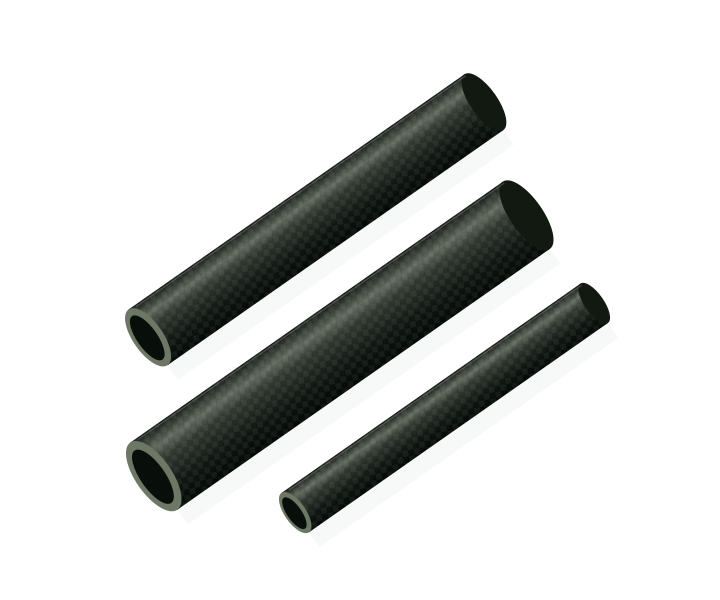
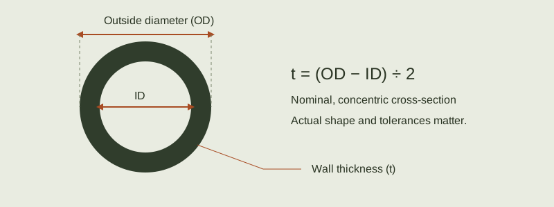
1 mm nominal wall
Wall = (outside diameter − inside diameter) ÷ 2.
Example dimensions, not a stock item.
START WITH YOUR REQUIREMENTS
Enter the nominal OD and ID in millimetres. We calculate the wall thickness for your enquiry. Use the notes for tolerances, load cases or a mating part.
Not sure about the layup? Select “Please advise” and describe the job. A 3K woven surface describes appearance; it does not establish a strength rating.
Any dimensions entered here are an enquiry, not confirmation of manufacturability. For a drawing in inches, include the original units and tolerances in your email.
Use these reference dimensions to start a custom enquiry. They are not a stock list or a limit on custom sizes. Specify your required cut length; material, tooling, tolerances and production feasibility are confirmed with the quotation.
Dimensions in millimetres unless shown otherwise. Scroll sideways on a small screen.
| Outside diameter / OD | Inside diameter / ID | Nominal wall | Your enquiry |
|---|---|---|---|
| 5 | 3 | 1 | |
| 6 | 4 | 1 | |
| 7 | 5 | 1 | |
| 8 | 6 | 1 | |
| 10 | 8 | 1 | |
| 10 | 9 | 0.5 | |
| 12 | 10 | 1 | |
| 12 | 11 | 0.5 | |
| 14 | 12 | 1 | |
| 16 | 14 | 1 | |
| 18 | 16 | 1 | |
| 20 | 18 | 1 | |
| 22 | 20 | 1 | |
| 25 | 23 | 1 | |
| 25 | 22 | 1.5 | |
| 30 | 27 | 1.5 | |
| 40 | 37 | 1.5 | |
| 50 | 47 | 1.5 | |
| 60 | 57 | 1.5 |

These directions describe reinforcement relative to the tube axis. They are a way to discuss requirements, not a universal stacking recipe.
Axial reinforcement contributes to stiffness along the tube. Its contribution matters in bending and axial loading, but it is not the whole design.
Circumferential reinforcement helps carry hoop-direction loads. Clamps and local pressure still need a suitable laminate and contact arrangement.
Off-axis reinforcement is relevant to shear and torsion. The amount, sequence and interaction with other layers depend on the loading case.
Layers are placed around a mandrel, allowing reinforcement directions to be arranged for the application. OD, ID, wall and finish still need separate requirements.
Continuous reinforcement is drawn through a forming process. Many standard profiles are predominantly axial; transverse and connection behaviour need attention.
A woven appearance, gloss or matt finish does not establish a load rating. Treat cut ends, holes, inserts and clamped areas as part of the design.
Use the receiving tube’s inside diameter and the sliding tube’s outside diameter. The example values are for explanation, not a recommended fit.
Minimum clearance uses the smallest receiving ID and largest sliding OD. Maximum clearance does the reverse.
This calculation does not approve an assembly. Ovality, straightness, surface finish, wear, temperature, overlap and the clamp design also affect fit and service performance.
State the finished length and its tolerance. If an end face locates another part, include the squareness requirement and datum on your drawing.
Give hole diameter, position, edge distance and orientation. Tell us where fasteners or clamps transfer load so the laminate and machining can be reviewed together.
Identify which diameter controls the fit. Specify the mating part, contact length and intended assembly method; nominal dimensions alone do not define a working joint.
Tell us your dimensions, application and quantity. Ask for material and layup, tooling, machining, finish, sample cost and delivery to be identified in the quotation. Price depends on the complete specification, not diameter alone.
Send a sketch or drawing, mating parts and loads or deflection targets if known. Flag every critical dimension.
Confirm the proposed construction and inspection points before sample manufacture. Weight and stiffness targets require an agreed design and verification method.
Agree the final specification, quantity, lead time, packing and shipping terms before production.
The nominal ID of the outer tube is 20 mm, so the nominal diametral clearance is zero. That is not a specified sliding fit. Allow for the actual tolerance stack, shape, finish and any guides.
A thicker wall changes mass and section geometry. The reinforcement, joint, length and loading still determine performance. Start from the failure mode or deflection requirement rather than thickness alone.
Send hole position and diameter, datums, edge distances and mating hardware. Specify any load transfer through the feature; an attractive machined edge alone is not an acceptance test.
MORE APPLICATIONS / SAME MANUFACTURING KNOW-HOW
You don’t need a complete specification to start a conversation. Tell us the application and what you know so far.
sales@fibreparts.com ↗